By Robert Tate, Automotive Historian and Researcher
Images Courtesy of the Robert Tate Collection
Originally published 12.18.19 (republished 12.24.25)
By Robert Tate, Award-Winning Automotive Historian/Researcher
Images Courtesy of the International Truck Archives Collection/Robert Tate Collection
Published 12.17.25
Read more: The Legacy of International Metro Delivery Trucks
Remembering the History of the General Motors Technical Center
By Award-Winning Automotive Historian and Researcher Robert Tate
Images courtesy of GM Heritage Archives & Special Collections
Published 12.10.2025
Read more: Remembering the History of the General Motors Tech Center
By A. Wayne Ferens
Published 12.3.2025 (Revised 12.4.2025)
Read more: Creative Industries of Detroit...Making Dreams Come True
By Robert Tate Award Winning Automotive Historian/Researcher.
Published 11.26.2025
Images courtesy of Robert Tate’s Automotive History Collection.
By Robert Tate Award Winning Automotive Historian and Researcher
Published 11.19.2025
Images Courtesy of GM Heritage Archives & Special Collections
Read more: See The USA In Your Chevrolet featuring Dinah Shore 1950’s-1960’s
By Robert Tate Award Winning Automotive Historian/Researcher
Published 11.12.25
Images Courtesy of Gordon Buehrig Archives.
Read more: The Tasco sportscar was a unique concept design from the 1940’s
by A. Wayne Ferens
Published 11.5.2025
Read more: Remembering Eugene "Bob" Gregorie: His Most Significant Designs At Ford Motor Co.
By A. Wayne Ferens
Published 10.29.2025
By Robert Tate, Award-Winning Automotive Historian and Researcher
Images Courtesy of the Ford Motor Company Archives
Published 10.22.2025
By Robert Tate, Award-Winning Automotive Historian and Researcher
Images Courtesy of the General Motors Heritage Archives
Published 10.15.2025
Read more: What Will the Next Generation Chevrolet Corvette Look Like?
By Robert Tate, Award-Winning Automotive Historian and Researcher
Images Courtesy of the Stellantis Chrysler Archives
Published 10.8.2025
By Robert Tate, Award-Winning Automotive Historian and Researcher
Images courtesy of the Stellantis Chrysler Archives
Published 10.1.2025
By Robert Tate, Award-Winning Automotive Historian and Researcher
Images Courtesy of the General Motors Heritage Archives
Published 9.24.2025
by Ron Alpern
Images Courtesy of the Reuther Library at Wayne State University and the Detroit Historical Society
Published 9.17.2025
By Robert Tate, Award-Winning Automotive Historian and Researcher
Images Courtesy of Stellantis Chrysler Archives
Published 9.10.2025
Read more: Chrysler Had Great Success with Their Muscle Car Advertising
by Brian Yopp, MotorCities' Deputy Director
Images Courtesy of the Gilmore Car Museum
Published 9.3.2025
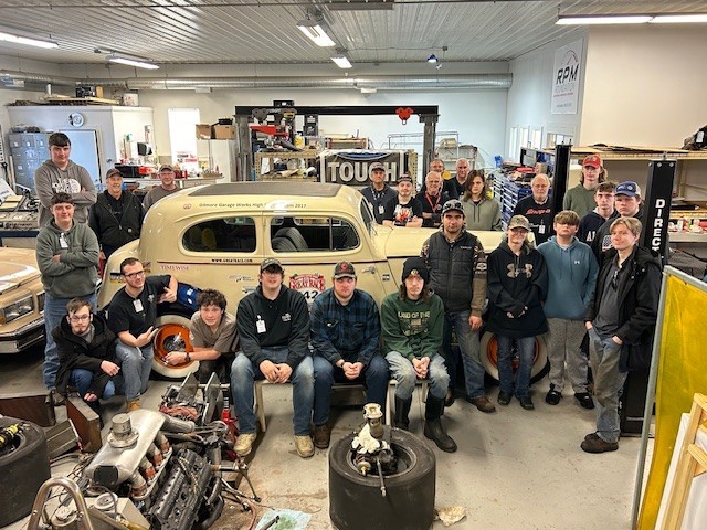 A recent group shot of the students and mentors participating in the Gilmore Garage Works program.
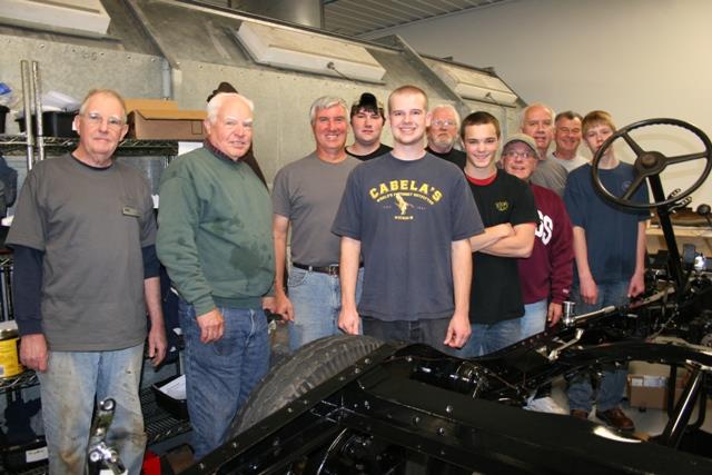 An earlier group of participants in the Gilmore Garage Works program
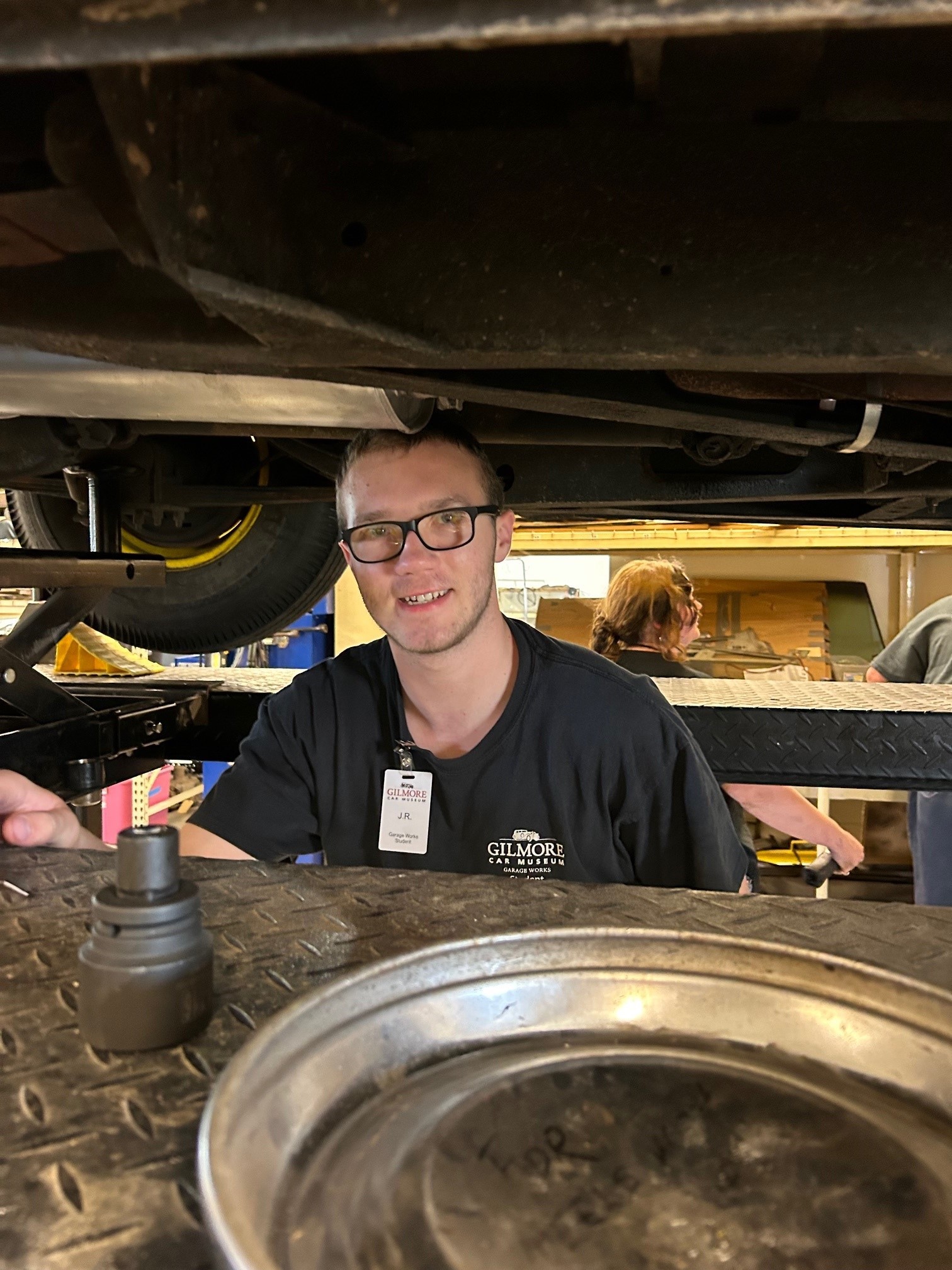 A recent student participant in the program
 The Gilmore Garage Works building
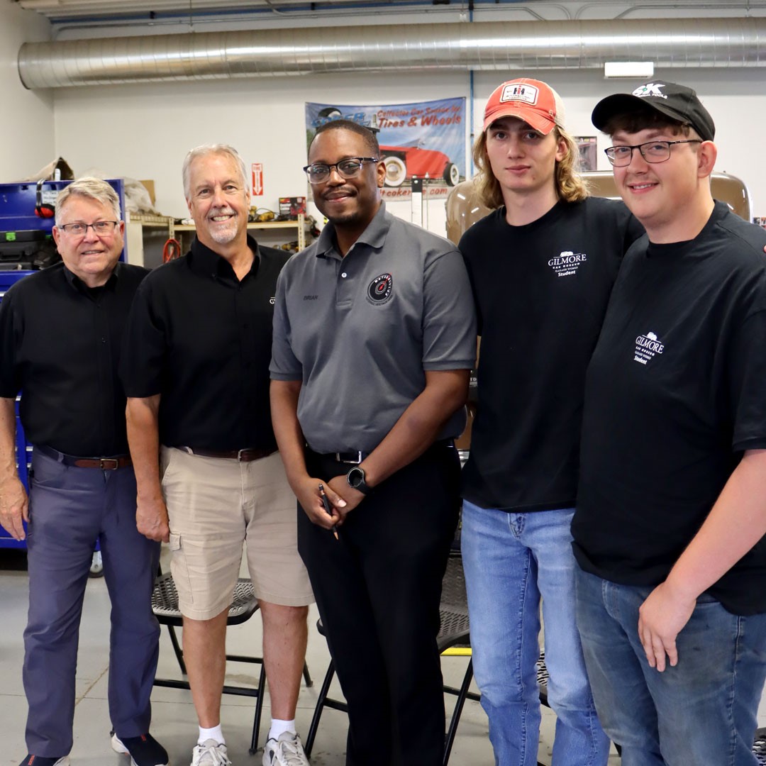 MotorCities Deputy Director Brian Yopp (center), flanked by the Gilmore Car Museum's Director of Education Fred Colgren and Garage Works Manager John Chapman (left) and students Eli and Conner (right)
by A. Wayne Ferens
Images Courtesy of the Ferens Collection, Motor Trend, and Road & Track
Published 8.27.2025
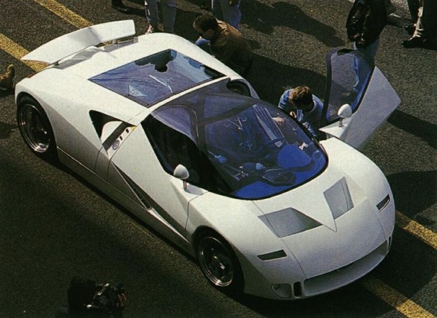 A view from above of the Ford GT 90 concept
Today's super cars are so advanced in engineering and technology -- even the word “exotic” is passe’. Words describing these new ultra-machines being tossed around the car industry include adjectives like extreme, hyper, super, or super-hyper. Yes, these new “exotics” are probably all of those things and more.
Look at some of today's “extreme machines” and see what they have in common -- those super Ferrari limited models like the LaFerrari, Lamborghini Veneno, Koenigsegg Regera, McLaren Senna, Bugatti Veyron and Pagani Zonda to name a few. For starters, all use advanced construction materials like carbon-fiber, high-strength aluminum, magnesium, titanium and other exotic materials. Most are hand-assembled using advanced structural adhesives or welding techniques. When automation is used, it is of the highest-tech most advanced computer controlled robotic manufacturing processes known to man.
When it comes to hyper-performance, many use radically designed V8s, V12s even V or W-16 cylinder engines with multi-valves, multi-cams, multi-turbos, etc. Some are even using advanced hi-tech hybrid systems that produce four-figure horsepower levels from their power units. Many of these super cars are not evolutionary, but revolutionary to say the least. So, when did this "hyper-revolution" start and who started it? Let's take a look back to the 1990s.
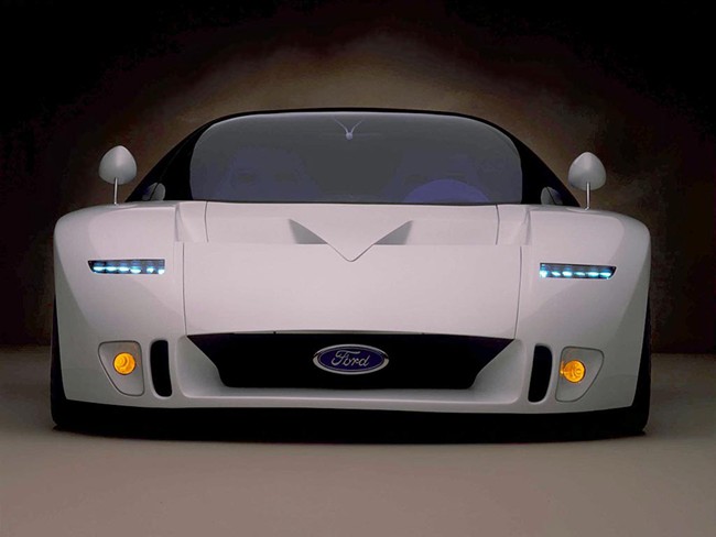 A front end view of the Ford GT 90 concept
One car comes to mind -- the Ford GT. No, not the early welded steel/fiberglass, cast iron carbureted V8 GT40 from the 1960s, but Ford's hyper-super-exotic concept car built in 1995 known as the GT-90. Some call it the greatest concept GT car ever made. Yes, it was made to run and drive. When a large high-volume automobile company like Ford Motor Company invests hundreds of thousands, even millions (estimates of $3-million for the GT-90) into a “dream car,” one must dream down the road so to speak.
Starting with some super car basics -- as used in the then Ford-owned Jaguar, as in Jaguar XJ-220 -- Ford laid the foundation of the GT-90 on the XJs chassis and suspension, and also used the Jag’s smooth shifting five-speed manual transmission.
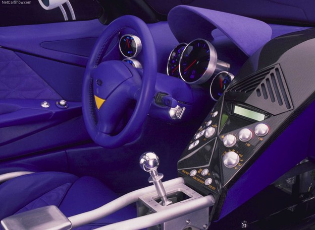 The cockpit of the Ford GT 90 concept
Ford molded it's “New Edge” designed body out of exotic and very expensive hand-laid, light-weight, high-strength, carbon-fiber material. This 3,200 lb. super car had subtle styling details reminiscent of the original GT40, especially on the front of the vehicle.
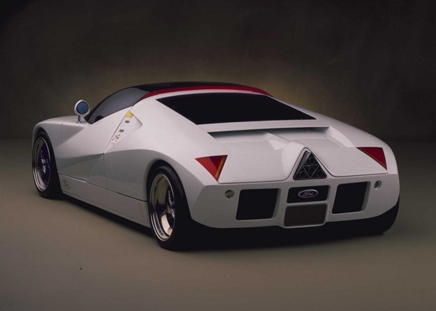 A rear view of the Ford GT 90 concept
To give it that mind-blowing super hi-performance, Ford sliced and diced two of its modular 4.6-liter fuel-injected V8s as used in the Lincoln and created a 6.0-liter DOHC 48 valve, quad-turbo (Garrett T2s) aluminum V-12 -- pumping out 720 horsepower and 660 lb. ft. of torque from its mid-engined power unit. Other hi-tech features included touch-panel entry, passing car sensors, speed-activated air dam and a gorgeous spacious blue oval-colored interior with individual gauge pods and a multi-control center console.
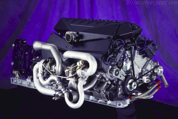 The powerful engine that drove the concept to high-performance heights
First debuted at the 1995 Detroit Auto Show, the Ford GT-90 super car became an instant sensation. On the track, it produced performance numbers in the range of 0 - 100 mph in six seconds and a top speed of 230 mph. If the super or hyper name fits, wear it!
Ford never intended to put the car into production, but the company continued the “New Edge” design through the 2000s on many of its popular production models. Was this just a styling exercise, or did Ford secretly intend to build an exotic super performance hyper-car? I mean a ultra-super-performance-exotic-hyper car like the new Ford GT that can be purchased through special order -- in limited numbers of course ...
Bibliography
Motor Trend, December 1, 1995
Road & Track, April 1995
By Robert Tate, Award-Winning Automotive Historian and Researcher
Images Courtesy of General Motors Heritage Archives, Spotlight Hobbies Inc. and Barrett-Jackson Auction Company
Published 8.20.2025
Read more: Remembering the Great-Looking 1969 Chevrolet Chevelle
By Robert Tate, Award-Winning Automotive Historian and Researcher
Images Courtesy of the Pebble Beach Concours d’ Elegance, Auburn Cord Duesenberg Museum, Black Hawk Museum and Ruxton Automotive Archives
Published 8.13.2025
By Robert Tate, Award-Winning Automotive Historian and Researcher
Images courtesy of the Stellantis Chrysler Archives and General Motors Heritage Archives
Published 8.6.2025
Read more: Bryan Nesbitt Becomes General Motors' 8th Head of Design
By Jeffrey D. Brasie
Images Courtesy of Checker Motor Cars and the Checker Car Club of America
Published 7.30.2025
By Robert Tate, Award-Winning Automotive Historian and Researcher
Images Courtesy of the Stellantis Chrysler Archives
Published 7.23.2025
Read more: The 1941 Chrysler Thunderbolt was an Early Concept Model
By Robert Tate, Award-Winning Historian and Researcher
Images Courtesy of the General Motors Heritage Archives
Published 7.16.2025
By Robert Tate, Award-Winning Automotive Historian and Researcher
Images Courtesy of the Robert Tate Collection
Published 7.9.2025
by A. Wayne Ferens
Images Courtesy of the Ferens Collection
Published 7.2.2025
by A. Wayne Ferens
Images Courtesy of Ford Motor Company, The Henry Ford, the Ferens Collection and the Nixon Library & Museum
Published 6.25.2025
By Robert Tate, Award-Winning Automotive Historian and Researcher
Images Courtesy of General Motors Heritage Archives
Published 6.18.2025
Read more: Remembering "Mr. Corvette," Engineer Zora Arkus-Duntov
By Robert Tate, Award-Winning Automotive Historian and Researcher
Images Courtesy of Henry Ford Media Center Archives and The Henry Ford
Published 6.11.2025
Read more: Remembering Edsel Ford's Lincoln Designs from the 1940s
By Robert Tate, Award-Winning Automotive Historian and Researcher
Images Courtesy of Stellants Chrysler Archives
Published 6.4.2025
By Jeffrey D. Brasie
Images Courtesy of the Corvette Club, Marlin Auto Club and the Cuda Brothers
Published 5.28.2025
By Robert Tate, Award-Winning Automotive Historian and Researcher
Images Courtesy of Ford Motor Company Archives, Motor Authority Auction, CT Pony Parts, Mecum Auctions
Published 5.21.2025
Read more: Remembering the 1969 Mustang Shelby GT 350/500 Models
By Robert Tate, Award-Winning Automotive Historian and Researcher
Images Courtesy of Stellantis Chrysler Archives, Heacock Classic, The Robert Tate Collection
Published 5.14.2025
Read more: Stellantis to Celebrate 100 Years of Chrysler History
By Robert Tate, Award-Winning Automotive Historian and Researcher
Images Courtesy of General Motors Media Archives/Bill Porter Personal Portfolio
Published 5.7.2025
Read more: Remembering Bill Porter, Great GM Designer & Auto Historian
by A. Wayne Ferens
Images Courtesy of Ford Motor Company Archives and Ferens Collection
Published 4.30.2025
By Robert Tate. Award-Winning Automotive Historian and Researcher
Images Courtesy of General Motors Media Archives
Published 4.23.2025
Read more: Remembering the Oldsmobile Aerotech Concept by Ed Welburn
By Robert Tate, Award-Winning Automotive Historian and Researcher
Images Courtesy of the General Motors Media Archives
Published 4.16.2025
Read more: Early Chevy Corvette Advertising Was Great for Framing
By Robert Tate, Award-Winning Automotive Historian and Researcher
Images Courtesy of Moulton Taylor Aerocar Archives
Published 4.9.2025
Read more: Remembering Moulton B. Taylor, Creator of the Flying Aerocar
By Robert Tate, Award-winning Automotive Historian and Researcher
Images Courtesy of Ford Motor Company Media Archives
Published 4.2.2025
Read more: Remembering the 1970 Mercury Cougar "El Gato" Show Car
by A. Wayne Ferens
Photos from the Henry Ford Heritage Association, the Ferens Collection and the Automobile Reference Collection
Published 3.26.2025
Read more: Remembering Detroit's Automotive "Golden Jubilee" in 1946
By Robert Tate, Award-Winning Automotive Historian and Researcher
Images Courtesy of Cord Museum Archives
Published 3.19.2025
Read more: The Cord Automobiles Offered the Best Designs & Great Ads
By Robert Tate, Award-Winning Automotive Historian and Researcher
Images Courtesy of The Peter Helck Collection
Published 3.12.2025
Read more: Remembering the Great Automotive Artist, Peter Helck
By Robert Tate, Award-Winning Automotive Historian and Researcher
Images Courtesy of General Motors Heritage Archives
Published 3.5.2025
Read more: Remembering the Pontiac Fiero, an Exciting Automobile
by A. Wayne Ferens
Images Courtesy of the Ford Motor Company and the Ferens Collection
Published 2.26.2025
By Robert Tate, Award-Winning Automotive Historian and Researcher|
Images Courtesy of Stellantis North American Archives, The Coolist.com, and the Robert Tate Collection
Published 2.19.2025
Read more: The 1960 Plymouth XNR was a Classic Concept by Virgil Exner
By Robert Tate, Award Winning Automotive Historian and Researcher
Images Courtesy of the General Motors Heritage Archives
Published 2.12.2025
Read more: Remembering General Motors' Class of 1967, a Very Good Year
by A. Wayne Ferens
Images Courtesy of the Ferens Collection
Published 2.5.2025
by A. Wayne Ferens
Images Courtesy of the Historical Society of Western Pennsylvania, Gulf Oil and the Ferens Collection
Published 1.29.2025
By Robert Tate, Award-Winning Automotive Historian & Researcher
Images Courtesy of the Pontiac Transportation Museum, MotorCities and the Robert Tate Collection
Published 1.22.2025
Read more: The New Pontiac Transportation Museum Displays Great History
By Robert Tate, Award-Winning Automotive Historian and Researcher
Images Courtesy of Stellantis North American Archives and Davidsclassiccars.com
Published 1.15.2025
Read more: Remembering the Popular 1970 Chrysler Hurst Edition
By Robert Tate, Award-Winning Automotive Historian and Researcher
Images Courtesy of the Henry Ford Media Center Archives
Published 1.8.2025
by A. Wayne Ferens
Images Courtesy of Ford Motor Company and the Ferens Collection
Published 1.1.2024